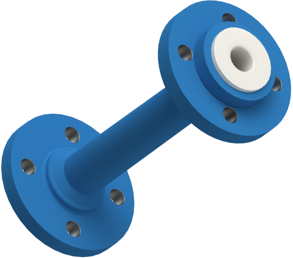
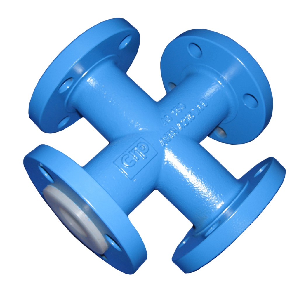
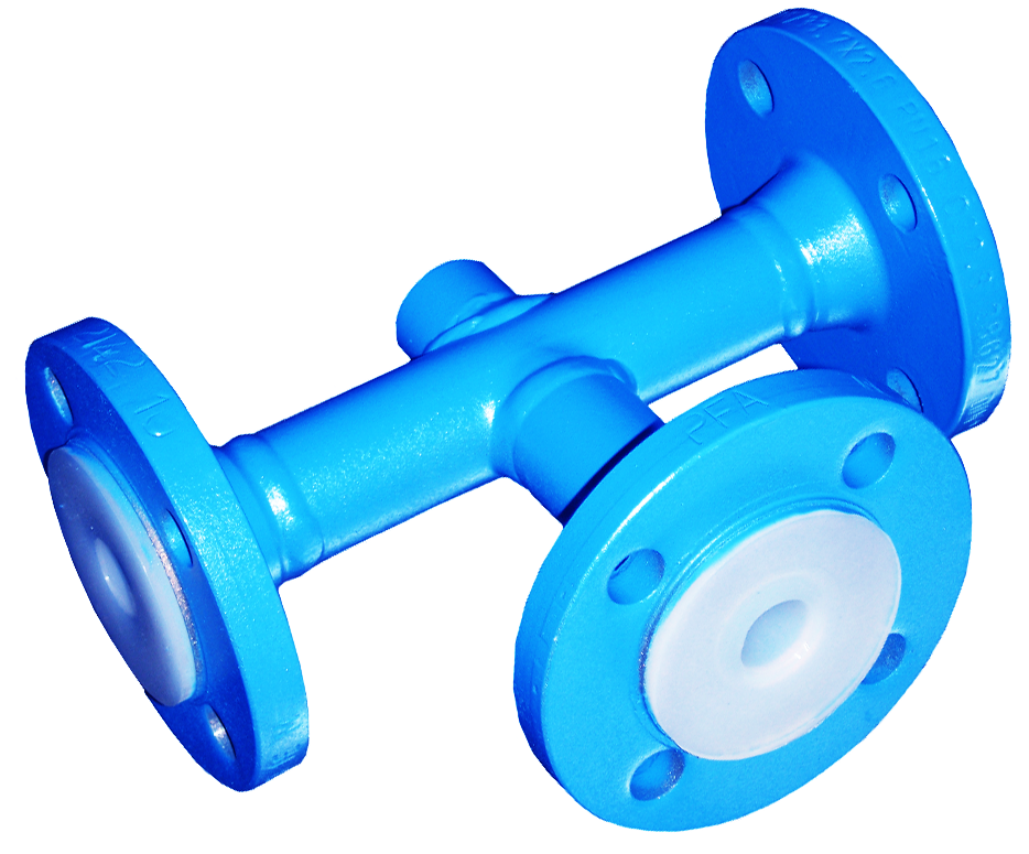
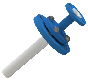
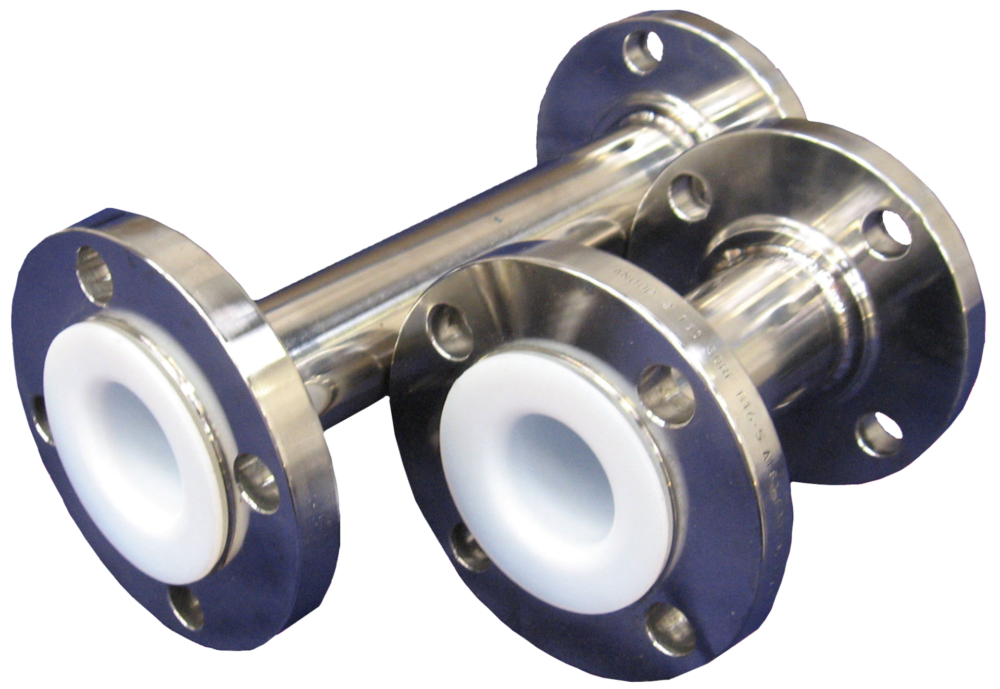


PTFE and PFA lined steel Reducing Flanges
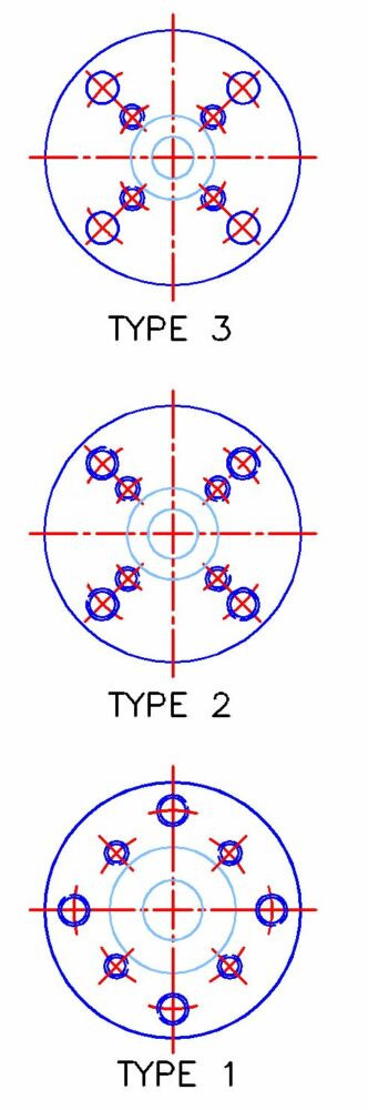
Reducing flanges can be grouped into 3 main configurations– Type 1, 2 & 3. The configuration is dictated by the proximity of the small bore bolt holes to the large bore bolt holes. Each type is designed so that they do not clash and that the nuts can be fitted successfully. Type 3 flanges have through holes for the large bore bolts and are used where there is a significant reduction in bores. Where the reduction is not so great and the periphery of the smaller bore mating flange would impinge on the nuts then a type 2 flange is employed with threaded bolt holes negating the use of nuts. Finally where the reduction in bores is quite small the bolt holes have to be staggered on / off centres so that they don’t clash – a type 1 reducing flange.
As a general rule, a type 3 is the design of choice, if this cannot be achieved, a type 2 should be specified, and if this doesn’t work, then a type 1. If you have site reasons for wanting to select another style, then a type 1 or 2 will always work where a type 3 does and a type 1 where a type 2 does.
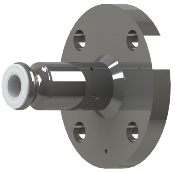
As a general rule CRP reducing flanges are supplied with a tapered bore, but occasionally due to method of manufacture a parallel bore is supplied. If you have a particular requirement e.g. parallel bores are often specified when equipment one one side of the flange requires more support then please specify this.
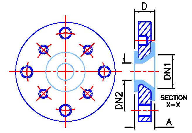
The dimensions below are to suit ASME 150 flange connections, we can supply the threaded holes to suit metric series bolts upon request.
| Nominal Size | Type | Ø A | D | Liner Thickness | |
|---|---|---|---|---|---|
| DN1 | DN2 | ||||
| In. | In. | In. | In. | In. | |
| 3/4″ | 1/2″ | 1 | 3.88 | 1.18 | 0.20 |
| 1″ | 1/2″ | 1 | 4.25 | 1.18 | 0.20 |
| 1″ | 3/4″ | 1 | 4.25 | 1.18 | 0.20 |
| 1.1/2″ | 1/2″ | 1 | 5.00 | 1.18 | 0.20 |
| 1.1/2″ | 3/4″ | 1 | 5.00 | 1.18 | 0.20 |
| 1.1/2″ | 1″ | 1 | 5.00 | 1.18 | 0.20 |
| 2″ | 1/2″ | 3 | 5.98 | 1.18 | 0.20 |
| 2″ | 3/4″ | 2 | 5.98 | 1.18 | 0.20 |
| 2″ | 1″ | 2 | 5.98 | 1.18 | 0.20 |
| 2″ | 1.1/2″ | 1 | 5.98 | 1.18 | 0.20 |
| 3″ | 3/4″ | 3 | 7.50 | 1.38 | 0.20 |
| 3″ | 1″ | 3 | 7.50 | 1.38 | 0.20 |
| 3″ | 1.1/2″ | 2 | 7.50 | 1.38 | 0.20 |
| 3″ | 2″ | 1 | 7.50 | 1.38 | 0.20 |
| 4″ | 3/4″ | 3 | 9.00 | 1.38 | 0.20 |
| 4″ | 1″ | 3 | 9.00 | 1.38 | 0.20 |
| 4″ | 1.1/2″ | 3 | 9.00 | 1.38 | 0.20 |
| 4″ | 2″ | 3 | 9.00 | 1.38 | 0.20 |
| 4″ | 3″ | 2 | 9.00 | 1.38 | 0.20 |
| 6″ | 3/4″ | 3 | 11.02 | 1.57 | 0.20 |
| 6″ | 1″ | 3 | 11.02 | 1.57 | 0.20 |
| 6″ | 1.1/2″ | 3 | 11.02 | 1.57 | 0.20 |
| 6″ | 2″ | 3 | 11.02 | 1.57 | 0.20 |
| 6″ | 3″ | 3 | 11.02 | 1.57 | 0.20 |
| 6″ | 4″ | 2 | 11.02 | 1.57 | 0.20 |
| 8″ | 1″ | 3 | 13.50 | 1.38 | 0.20 |
| 8″ | 1.1/2″ | 3 | 13.50 | 1.38 | 0.20 |
| 8″ | 2″ | 3 | 13.50 | 1.57 | 0.20 |
| 8″ | 3″ | 3 | 13.50 | 1.57 | 0.20 |
| 8″ | 4″ | 3 | 13.50 | 1.57 | 0.20 |
| 8″ | 6″ | 2 | 13.50 | 1.57 | 0.20 |
| 10″ | 1″ | 3 | 15.98 | 1.38 | 0.10 |
| 10″ | 1.1/2″ | 3 | 15.98 | 1.38 | 0.10 |
| 10″ | 2″ | 3 | 15.98 | 1.38 | 0.10 |
| 10″ | 3″ | 3 | 15.98 | 1.38 | 0.10 |
| 10″ | 4″ | 3 | 15.98 | 1.38 | 0.10 |
| 10″ | 6″ | 3 | 15.98 | 1.38 | 0.10 |
| 10″ | 8″ | 2 | 15.98 | 1.38 | 0.14 |
| 12″ | 1″ | 3 | 19.02 | 1.38 | 0.14 |
| 12″ | 1.1/2″ | 3 | 19.02 | 1.38 | 0.14 |
| 12″ | 2″ | 3 | 19.02 | 1.38 | 0.14 |
| 12″ | 3″ | 3 | 19.02 | 1.38 | 0.14 |
| 12″ | 4″ | 3 | 19.02 | 1.38 | 0.14 |
| 12″ | 6″ | 3 | 19.02 | 1.38 | 0.14 |
| 12″ | 8″ | 3 | 19.02 | 1.38 | 0.14 |
| 12″ | 10″ | 2 | 19.02 | 1.38 | 0.14 |
| 14″ | 12″ | 1 | 20.98 | 1.57 | 0.14 |
| 16″ | 12″ | 3 | 23.50 | 1.57 | 0.14 |
| 16″ | 14″ | 2 | 23.50 | 1.38 | 0.14 |