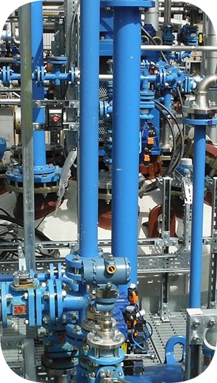


Introduction To Lined Piping
The purpose of this section is to present to the engineer a basic understanding of the world of fluoropolymers. We touch on all of the key considerations for lined equipment, specifically homing in on lined pipe and fittings – as the dominant system element.
In our experience, few engineers are exposed to these materials sufficiently in their working lives to understand the considerations that need to be made in the specification, design, installation and use of equipment.
In a typical lined equipment specification: metals specifications will be quoted, weld test procedures documented and materials certification demanded. However, when it comes to the fluoropolymer element, the specification is often found wanting, with often at best some passing reference to PTFE or Teflon made.
An Introduction to PTFE
How it was discovered
PTFE was discovered by a team led by Dr Roy Plunkett of the DuPont Company in 1938. He was experimenting with tetrafluoroethylene for the synthesis of new refrigerants.
One morning, he returned to the laboratory to check the pressure on a cylinder of TFE gas prepared for an experiment and discovered that there was none. Yet, the valve had not appeared to leak and the cylinder had not lost any weight. On removing the valve and shaking the cylinder he found a few grams of a waxy white substance, the first polymer of tetrafluoroethylene.
An analysis of the powder found it to be PTFE (Polytetrafluoroethylene). He determined that it has some amazing properties – it could not be dissolved in any solvent, acid or base chemical, was extremely slippery and had enormous electrical resistance.
The material was put on the official secrets list and was used in the Manhattan Project (the atom bomb) for uranium enrichment using uranium hexafluoride gas. (1) After the Second World War it became commercialised with ICI commencing production in Europe under licence in 1947.
What is PTFE?
PTFE is a plastic – that is capable of being shaped or moulded with or without the application of heat. It comprises a number of repeat units of a monomer (a compound of low molecular weight to form a polymer and is described specifically as a fluoropolymer consisting of carbon (C) and fluorine (F) atoms, with each carbon atom having two fluorine atoms attached to it.
Each of the carbon atoms is joined to the next to form a long chain many thousands of atoms long wrapped in a tight helix of fluorine atoms. The carbon-carbon bond is in its own right quite strong, but the fluorine-carbon bond is one of the most powerful known. (2)
The size of the fluorine atoms allows a tight sheath to be formed around the carbon atoms creating a structure which is exceedingly difficult to attack and is mechanically very secure. (3)
When Fluorine atoms form part of a molecule, they repel other elements – hence why nothing sticks to PTFE. These two properties – chemical inertness and anti-adhesion are the most useful attributes for fluoropolymer equipment supplied into industries handling corrosive materials.
Key Properties of PTFE
PTFE is electrochemically, biochemically, enzymatically and chemically virtually inert. It is easier to describe those substances that can attack PTFE than those that cannot. (4)
These comprise elemental fluorine and some tri-fluoride compounds – which are chemically close brothers of PTFE, and molten alkali metals such as sodium and potassium. There are no known solvents that will dissolve PTFE.
All of these important, useful properties (that is not more than 15% loss of chemical resistance) are retained at up to 390° F giving PTFE the highest retention of its chemical properties of any known plastic-like material.
It is important to note that product literature characterises properties as being retained at 500° F; this is technically true, but is only appropriate for laboratory testing. In real applications other PTFE attributes prevent such performance.
PTFE does not absorb any materials as it is non-wetting. Recent studies on different materials showed a 99%, 99% and 98% removal of biofilms of Pneumonia, E. coli and Cholera respectively from PTFE, compared with 67%, 25% and 56% from stainless steel or 89%, 0% and 0% for borosilicate glass.(4)
The smoothness of the surface combined with its hydrophobicity and inertness makes it an ideal product for multi-purpose plant where cross-contamination could be an issue. For example, in the production of ultra-pure sulphuric acid one of our customers has achieved cleanliness levels of better than one half of a part per billion – or put another way the equivalent of three and a half people in the world population.
Disadvantages of PTFE
Unfortunately, PTFE comes with a number of unhelpful properties when used for conveying corrosive material and it is necessary to understand these in order to manage them.
- Most importantly PTFE is mechanically weak, making it difficult to construct things from and so it often requires mechanical support. Because of a lack of intermolecular forces the material is soft and easily abraded. This means that erosion is a potential concern, as is the property of creep or cold flow under load. Like all plastics PTFE is subject to permeation by certain types of molecule and where this is likely to occur, it requires managing. Although thermally stable from a chemical resistance perspective, it has a high and variable expansion rate of approximately ten times that of steel.
- Also, the electrical resistance properties of PTFE can be both a benefit and a hinderance. In the lining of electromagnetic flow-meters it is of huge benefit, but in transferring poorly conducting solvents there is the potential to develop electrostatic charging that must be dealt with.
- Finally, one cannot ignore the fact that PTFE is expensive. The processes of refining TFE require large amounts of energy and are complex and dangerous. In the last ten years two global scale processing plants have been destroyed by explosion. As a result, there are not many processors in the world, new applications are consuming materials and demand has always outstripped production.
However, fluoropolymers are the materials of choice for the process industry, serving as linings for vessels, piping, pumps, valves, columns, column internals, hoses, expansion joints, seals and gaskets. (5)
They provide durable low maintenance alternatives to exotic metal alloys, offering thermal stability for use at high temperatures and, because they do not react with the process liquors, they prevent contamination.
The Fluoropolymer Family
From the very first discovery of PTFE polymer scientists have been striving to develop new materials which have all the good attributes of PTFE but are cheaper and can be processed by conventional melt processing techniques. PTFE has to be cold pressed into shape and sintered. (6)
So far, despite some valiant attempts they have failed in at least one or more of the key areas of temperature range, chemical resistance, ease of processing and reduced cost. The only material matching the chemical, temperature and electrical properties of PTFE is PFA (perfluoroalkoxy) but its cost is roughly two to three times that of PTFE and it is difficult to process well.
These developments have spawned a whole family of materials, some of which have been highly successful. This family of Fluoropolymers is routinely split into two groups, the fully fluorinated materials (perfluoropolymers) and the partially fluorinated ones containing hydrogen and/or chlorine. (7)
In the fully fluorinated group are PTFE, PFA and FEP (fluorinated ethylene propylene) whose molecules are made up almost entirely of Carbon and Fluorine atoms. All are characterized by excellent chemical resistance, superb electrical properties, a good working temperature range and low friction. They are however mechanically weak, difficult to process and expensive.
FEP was the first (1960) of these PTFE alternatives but this material is no match for PTFE at temperatures above 302° F. In lined pipework FEP is now rarely seen but continues to be widely used as a thin unbonded vessel lining, and when combined with a knitted glass fibre backing as a bonded laminate. PFA followed in 1972 and despite its cost has been universally accepted as the melt processable alternative to PTFE, matching it in almost every respect and having greater permeation resistance and a better surface finish.
The partially fluorinated materials which are sometimes referred to as the engineering fluoropolymers have molecular structures where a significant number of the Fluorine atoms found in PTFE are replaced by Chlorine and/or Hydrogen atoms. This improves mechanical strength and processability; hence the term engineering polymer. They can be fabricated into self-supporting structures; are generally cheaper than the fully fluorinated materials and for the large part much more easily processed by conventional thermo plastic techniques.
These mechanical improvements come at significant cost in terms of loss of chemical resistance and temperature range together with some undesirable changes in frictional and electrical properties. The partially fluorinated group includes the well-known PVDF (Kynar and Solef), ETCFE (Halar) and ETFE (Tefzel). Some of these can be bonded directly onto metal substrates by melt fusion techniques. Many are offered as laminates for bonding to steel with adhesives or for the construction of other structures by reinforcing with composites of Glass Fibre and Resin.
The partial materials have good properties but in all but the rarest of circumstances cannot match the performance capability of PTFE/PFA lined pipework systems. Because of this lower performance and the need for a universal lined pipe system, the partial members of the fluoropolymer family are now rarely seen as pipe liners. Most designers and plant engineers opt for the comfort of the best system available, the fully fluorinated PTFE and PFA.
Processing Technologies
Processing can have more impact upon the performance of materials made from fluoropolymers than with other types of polymers. (8)
For PTFE there are four key technologies available for manufacturing products. These are paste extrusion, isostatic moulding, ram extrusion and tape winding. For melt processable materials products can be manufactured by thermoplastic extrusion and transfer moulding.
Each of these technologies suits particular types of product and has advantages and disadvantages – which will be considered specifically in relation to the conveyance of corrosive substances.
Simple Geometries of PTFE
Paste extrusion is used for the production of hoses, pipe liners and short curved or reducing pieces for pipe fittings. It involves taking a fine powder PTFE; called this because of the small grain size and the narrow standard distribution of this grain size. This is chilled and a processing aid lubricant is added. It is warmed to allow the lubricant to fully wet the material, pressed into a billet, and extruded through an orifice to provide a circular section.
The piece is finally loaded into an oven and sintered. It is the most expensive PTFE production process, but provides the smoothest surface finish, best mechanical performance and highest rates of permeation resistance.
Isostatic moulding uses coarser granular PTFE powders to fill a rubber bag within a pressure pot. The bag is placed over a mandrel which forms the internal diameter of the tube and using water pressure a loose powder fill is compressed onto the mandrel.
It is subsequently removed from the vessel and placed in an oven for sintering. Its advantage is that it is a less expensive process, but the PTFE has a coarse surface finish and the random molecular orientation of the PTFE molecules reduces its permeation performance compared to paste extruded PTFE pipe liners and PFA lined fittings. CRP do not recommend this processing method for permeant duties, or those requiring cleanliness or cleanability.
Ram extrusion is now little practised for pipe liners; it is only seen in emerging economies. This process uses a pre-sintered granular powder and pushes a small amount into a vertical die and thumps it down, out through the base of the die and into a continuous oven. This can produce layering or laminations depending on the fill per machine stroke.
As a very slow process there is a temptation to put more material in and this gives differential compression and areas of poor compaction. The product can therefore be quite permeable and is not recommended. Similarly tape winding is no longer widely practiced. Here a paste extruded “tape” is wound tightly over a mandrel and subsequently sintered. This method provides a low tooling cost and versatility, but is prone to delamination when poorly fabricated.
Complex Geometries of PTFE
For creating more complex shapes there are two key choices:
- using PTFE in the isostatic moulding process
- moulding in PFA using transfer moulding.
The isostatic process is similar to that used in pipe liners, except that the steel outer shell may be used as part of the tooling and the powder pressed into the inside rather than onto separate tooling. The isostatic process has a cost advantage, but again the product has a lower permeation performance, a rough surface and is not a tight fit inside the steel part. This means that any vacuum performance can only be obtained through wall thickness, which on smaller parts is difficult to obtain as the gap into which the loose material can be filled is limited and requires a compression ratio of 3:1.
Transfer moulding is an isothermal process in which tooling and steel components (which effectively form the outside of the tooling) are heated in an oven to 698° F for several hours. Molten PFA is then pushed relatively gently into the component, filling the void. The materials fill and tooling need to be able to manage the 30% shrinkage involved in the cooling of PFA back to solid and not to stress the material in doing so. PFA is an expensive material, but has the highest performance of all fluoropolymers – being better on permeation than even paste extruded PTFE and having the smoothest surface of all. It also has the advantage of translucency, meaning that any processing problems are usually visible in the lining. There are many grades of PFA available and it is critical to specify those that have the lowest melt flow rates, essential for corrosion performance.
Performance of PTFE
It is crucial to ensure that the lined piping and fittings have the highest performance level, as the core element of a fluoropolymer lined process.
This enables the plant to be multi-purpose, equipment to be reused with confidence and offers the most process safety. Inevitably other elements such as pumps, valves, vessels and columns have characteristics which affect performance but are outside the scope of this paper.
Any discussion of performance needs to consider three elements of the lined piping system. These are the metal surrounds of pipe and fittings, the fluoropolymer used to line them and the processing method (and thereby the type of fit between the metal and the lining). The metal surround provides the mechanical strength for the system, lining its corrosion performance.
Pressure
The pressure capability of a lined system is generally driven by the steelwork and here two global standards tend to dominate:
- the US standard ASME B16.5 Class 150
- the German DIN PN10 standards
Although both of these standards are 10 bar classifications, both allow pressures to a higher level (275 and 246 PSI respectively) depending upon the temperature and metal used. In reality many chemical processes are much more benign running at a few bars. If it is necessary to line higher rated systems such as Class 300, this is quite possible, but one must consider the potential for the lining to extrude out of joints and the manufacturer should be consulted.
Temperature Limits
The lower operating temperature limit is usually set by the metal housing and -20° F is the typical lower working limit, however with the correct supporting materials and design PTFE is perfectly capable of working at cryogenic temperatures.
The upper temperature limit is set by the fluoropolymer, and as mentioned previously not by the “lab” specification, but the strength of the materials at temperature and 392° F is the usual maximum – and even this is quite challenging for the materials.
When selecting lined equipment however, one must think of the maximum and minimum temperatures, the potential for thermal shock and upset conditions.
Vacuum
Vacuum is not defined by the pressure classification of the piping, but by the ability of the liner supported by the housing to resist vacuum collapse. It is the most often ignored aspect of the system and consequently the most widespread source of failure.
Because of this “mechanical” attribute, larger line sizes will have a poorer vacuum performance and higher temperatures will reduce the liner strength. It doesn’t help that piping systems are really designed around positive pressure performance.
With PTFE paste and isostatic pipe linings a low-level interference fit of the liner in the steel tube can provide hoop support and help resist vacuum collapse.
With PFA moulded fittings, the liner thickness helps, but also moulded keyways in the steel housing assist.
With isostatically moulded fittings, it is only the liner thickness that defines the level of performance.
A good system should be capable of withstanding full vacuum (typically 0.00145 to 0.725 PSI absolute) at the maximum operating temperature (392° F) for line sizes up to and including 6″NB. Above this size it is usual, particularly with PTFE paste and isostatic components, to produce products for non-vacuum and vacuum duties. This is because the performance comes from using more PTFE, an expensive raw material, so if it is unnecessary then additional cost can be avoided.
These liners are usually referred to as ‘standard’ and ‘heavy duty’, but beware of using these terms as a surrogate for full or no vacuum performance as the term ‘heavy duty’ has no performance definition. The manufacturer should be capable of confirming the vacuum performance at different temperatures, having undertaken testing according to ASTM F1545.
Chemistry
The chemistry of the materials being carried can influence the design of the piping system. For permeant services, be they through absorption or diffusion, one must consider liner types, thicknesses and venting systems. For non-conducting flammable chemicals, static-dissipating materials may be advisable.
Always consider upset conditions, for example something nasty getting into the effluent stream and consider potential plant use in the future. It is always worth considering if PTFE/PFA lined piping is appropriate, there are certainly applications where its performance is too good.
Design & Performance Standards
Having considered the processes and materials, it is important to consider how to safeguard the choice of equipment and this should be done through specification, ideally referring to the appropriate international standards, but also wherever possible auditing the manufacturer.
In this niche industry it is not unusual for the vendor to masquerade as a manufacturer and source product from the world market with no traceability or control of manufacturing or materials standards.
The most important international standards are USA driven.
- ASTM F1545 (F423 the older, but similar standard is also quoted) covers the general specification of lined pipe including materials to be used, methods of fabrication and testing regimes – both production and type testing.
- The key fluoropolymer raw materials specifications are ASTM D3307 for PFA, D4894 for granular (isostatic) PTFE’s and ASTM D4895 for paste PTFE’s.
Key metals specifications depend on the manufacturer, but will include dimensional and materials specifications that plant engineers are quite familiar with. There are DIN equivalents to most of these specifications, but their use tends to be restricted to mainland Europe.
In terms of production performance, manufacturers should be capable of demonstrating compliance with the test regime of ASTM F1545 and maybe more, with production materials testing and finished product tests which may include electrostatic, hydrostatic and functional tests. They should also be capable of demonstrating traceability back to qualified raw materials.
Plant Design
Configuration
The crucial design aspect of lined piping is that the straight spools provide the variable element as it is relatively easy to manufacture these at different lengths, whilst the fittings are manufactured to standard dimensions, which all remain the same within a bore size.
This enables interchangeability without complete system redesign and provides the easiest and cheapest way of applying a product that has a complex manufacturing cycle and is unsuited to site running. Changes of direction are most cost-effectively accommodated by having rotating flanges on the pipe spools and fixed flanges on fittings.
Piping Support
This should essentially be as for a flanged steel piping system. It must not be over supported as it is possible to put unnecessary strain on the pipework and force flanges out of alignment.
Support close to flanges, ensuring that access for bolting and venting systems are not interfered with. Special pipe supports such as trunnions, brackets, sliders and feet should be factory fitted before lining – it is not acceptable to weld onto lined equipment.
Venting
This is a primary element of lined piping systems, its absence can be dangerous, but it is little understood. All PTFE and PFA lined equipment should have a venting system, most usually 0.19″ diameter holes in the steel pipe.
This serves two purposes:
- Firstly, without venting, any gases trapped between the lining and the steelwork will expand with an increase of temperature. These gases can arise by permeation through the lining. If they have nowhere to go the pressure on the back of the lining can cause it to collapse.
- Secondly, if for any reason the lining is damaged and leaks, the presence of a vent hole will provide an early warning of leakage and avoid the catastrophic failure of the piping.
With insulated lines, it is necessary to extend vents through the insulation by the addition of vent bosses and extension pieces. For permeant chemistries vent bosses are used with PTFE plugs. These serve to allow corrosive permeants which will become liquid on contact with the atmosphere to avoid corroding the metal around the vent and instead pass harmlessly through the PTFE plug and evaporate to atmosphere.
Bolting for PTFE lined equipment
Bolting for PTFE lined equipment should be clean, new, lightly lubricated and tightened in sequence to manufacturers recommend torques. Although these can be exceeded by 50%, over-torquing is not usually the solution to a leaking joint.
Stud bolts are preferable to machine screws as excess thread can be evened across the joint. It is always recommended to use two washers to ensure that torque readings are true. The standard threads for Class 150 are UNC and it is important to note that a number of components have blind or through tapped holes because of their configuration and as standard these have UNC threads rather than metric – which can be used satisfactorily.
Gaskets in a lined piping system
Gaskets should generally not be used in a lined piping system. PTFE is in itself a perfect gasket and the addition of a gasket can create another leak path and a stress point for the PTFE.
There are exceptions when joining PTFE to other equipment such as stainless steel, glass or graphite; or when frequently removing a lined item. In these cases, a PTFE envelope gasket should be used and not high load multi-directional gaskets which will cut the PTFE flare face off.
Falls & Efficiency
System falls can be generated by using rotating flanges, bolt holes and the general flexibility of the system. If necessary, tapered PTFE spacers can be fitted in joints. The only solution that does not work is offset flanges, which cannot be lined.
A lined piping system is very efficient and, in most circumstances, there are almost no frictional losses. However, there is still the pressure drop due to pushing a liquid through an orifice over a long distance and it is important to remember that lined piping is sized in nominal bores and a one inch lined pipe only has a 0.75″ bore. If there is a potential to develop a static charge, it can be managed by ensuring that line velocities are below 3′ per second for any multiphase liquid. (9)
Another velocity consideration is the weak material can become eroded or pushed aside at velocities greater than 16.5 yards per second.
Electrostatic Charging
This is always a possibility in a lined piping system and it is a particular hazard when working with an insulator of the efficiency of virgin PTFE – a 0.04″ film will insulate against 80,000 Volts. The principal source of charging in lined equipment is through tribo-charging. Here when two materials contact one another electrons flow between the materials leaving one negatively charged and one positively charged.
If they are good conductors, when separated the charge will flow back, but if one of the materials is a poor conductor this will not happen and the charge will get carried away on separation. The magnitude of tribo-charging will depend on how energetic the process is – the degree of contact area, speed of contact and the flow characteristics. This is important in lined equipment because processes may be conveying flammable materials and a spark of 0.25 millijoules provides sufficient energy to ignite most flammable vapours with potentially catastrophic consequences and a brush discharge in lined equipment can have energy of 2,000 millijoules. (10)
The simplest solution to electrostatic charging is to design this out of the plant by dropping material velocities below one yard per second. If this is not attainable then static-dissipating equipment should be considered. By the addition to PTFE of carbon powder and carbon fibre to PFA, the materials can be made static dissipative to a point where they will allow the charge to drain away harmlessly without damage to the chemical and mechanical performance of the linings.
Alternatives
Other alternatives such as sacrificial metal spades or static-dissipating spades are often specified at joints, but there is some doubt as to whether these actually work because of their small surface area, and indeed they may be of harm, providing a conductor to accept a spark. These black colored PTFE’s and PFA’s must not be confused with materials that are just colored black for cosmetic reasons which was a common practice in the early days of our industry.
For those worrying about food and drug contact from such materials, US Food and Drugs Administration approved grades of PTFE are available, but there are no approved grades of static dissipative PFA available.
Plant Earthing
This is the continuous grounding of the steel structures of the plant and must be done, for the dissipation of any charge whether it is caused by electrostatic charging, electrical equipment failure or lightning strike.
The recognized standard for earthing is that at no point should there be a resistance of greater than 10 ohms. This is conventionally achieved through copper earth bonding straps fitted to threaded studs or lugs welded to pipe and flanges.
Alternatively, it can be achieved through fitting serrated “star” washers to bolting and in the case of rotating flanges either tack welding the back of the flange to the pipe or fitting a large diameter “spikey” washer behind the flange, cutting into the stub end.
Insulation and Heat Tracing
Whilst it is important to remember that the pipe liner is an excellent insulator in its own right, lined piping can be insulated by all conventional means.
Vent holes must not be blocked, but extended through the insulation. Trace heating can be undertaken with steam, electricity, hot water or oil. If required, fully jacketed equipment is available for maintaining precise temperature control – cold or hot.
Flange Guards and Safety Shields
More European companies are undertaking risk assessments and specifying flange protection – the weak area of a lined system, with the adoption of the European Pressure Equipment Directive.
Guards are used in safety critical areas – beside and above walkways or roads to deflect any jet of liquid leaking and reduce the force or around PTFE bellows to provide some secondary protection.
Safety shields tend to be installed to identify and manage small material leakages and can be fitted with windows also manufactured from corrosion resistant materials or indicator papers for quick surveying.
Painting
To prevent atmospheric corrosion, carbon steel lined piping requires painting. Here there are a myriad of practices from a simple cheap “blast primer” to the most sophisticated multi-coat systems. In marine, hot, humid or other corrosive atmospheres it is sensible to specify a good zinc rich or even zinc silicate paint.
In Europe, high phosphorus electroless nickel coatings have proved popular when a customer is prepared to embark on a lifetime cost justification. None of the better finishes are cheap and there is a difficult choice between factory primer and site finishing and complete factory painting. With the former, the finish coat will never be applied as well as in the factory, but with the latter there is a strong likelihood of coating damage during the installation requiring extensive repainting anyway.
Equipment Selection
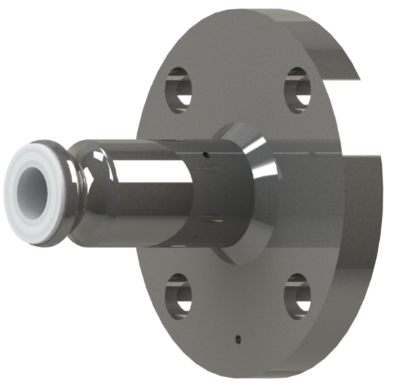
Pipe Spools
Pipe stools are generally constructed from carbon steel pipe although stainless steel has become popular for awkward or dangerous access areas where there is the potential for external corrosion, or for clean areas where paint flakes may contaminate product.
They are specified in 0.04″ increments, with the shortest lengths being around 4″ depending upon nominal bore and the longest lengths being 20′ for up to 6″NB bore and 10′ above this. Liner thickness requires consideration either for vacuum performance or for highly permeant services. It is possible to field fabricated pipe spools, but this is generally a slower, less controlled process than factory manufacture.
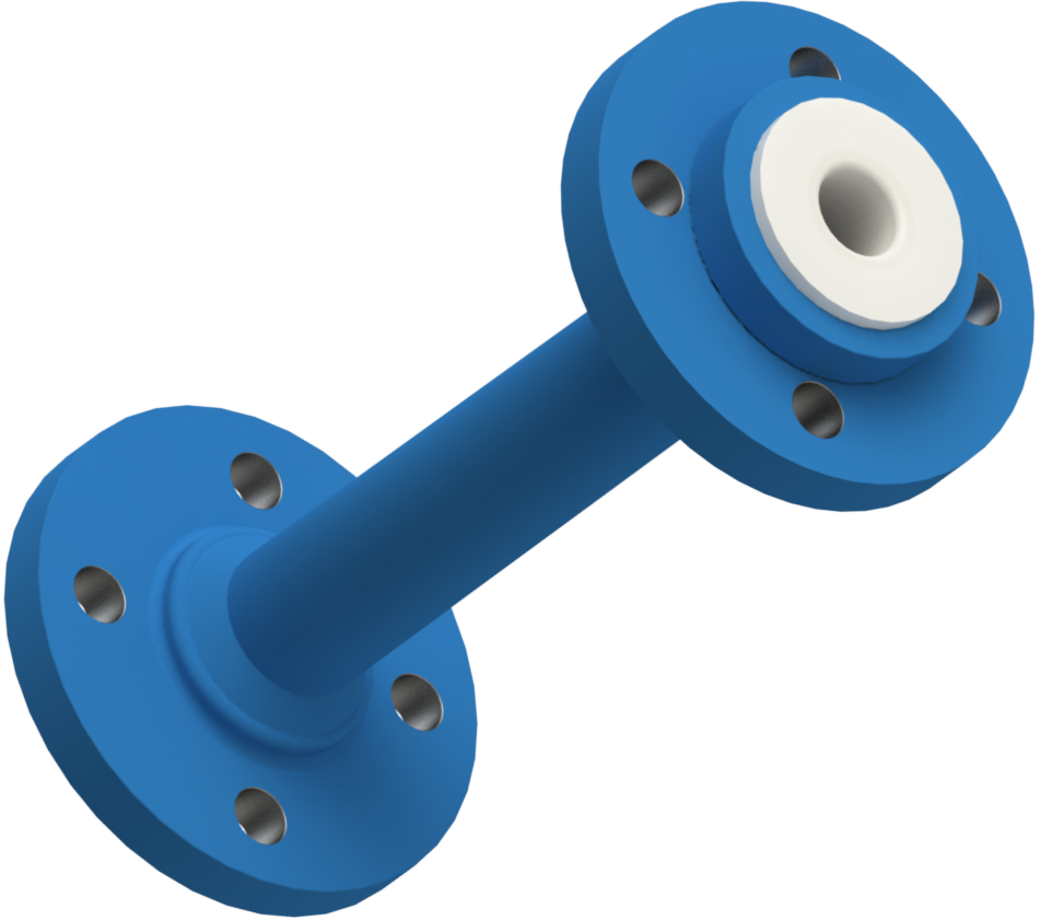
A good local manufacturer should be able to produce site “closing spools” in 24 to 48 hours. Spacers are a wafer component used where a pipe spool will not fit or to create a fall and are either solid PTFE up to 1″ or a lined piece of steel. They should be generally avoided because of the creep potential of unsupported PTFE.
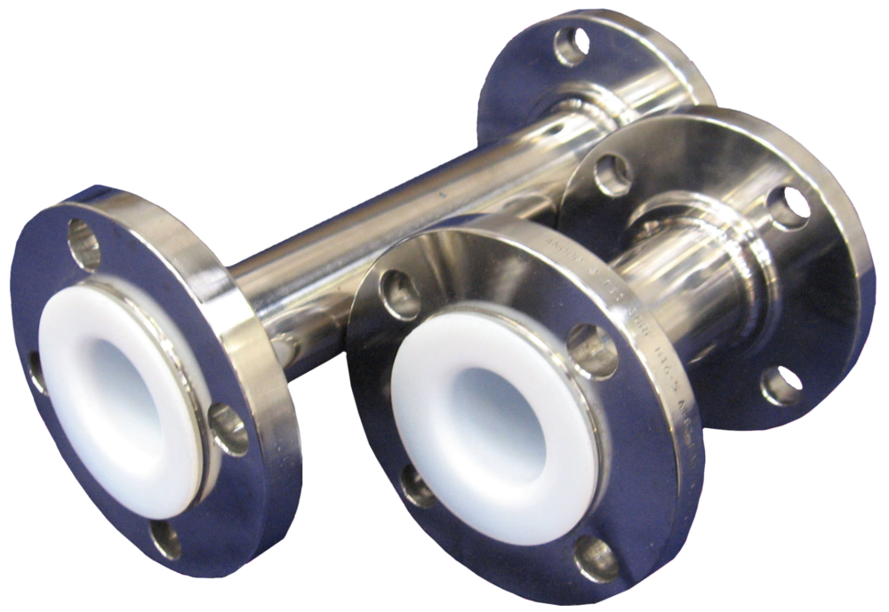
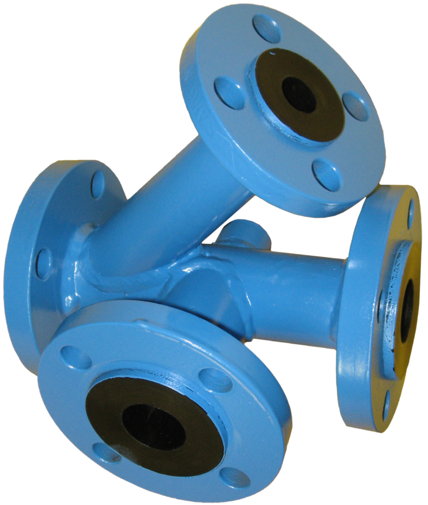
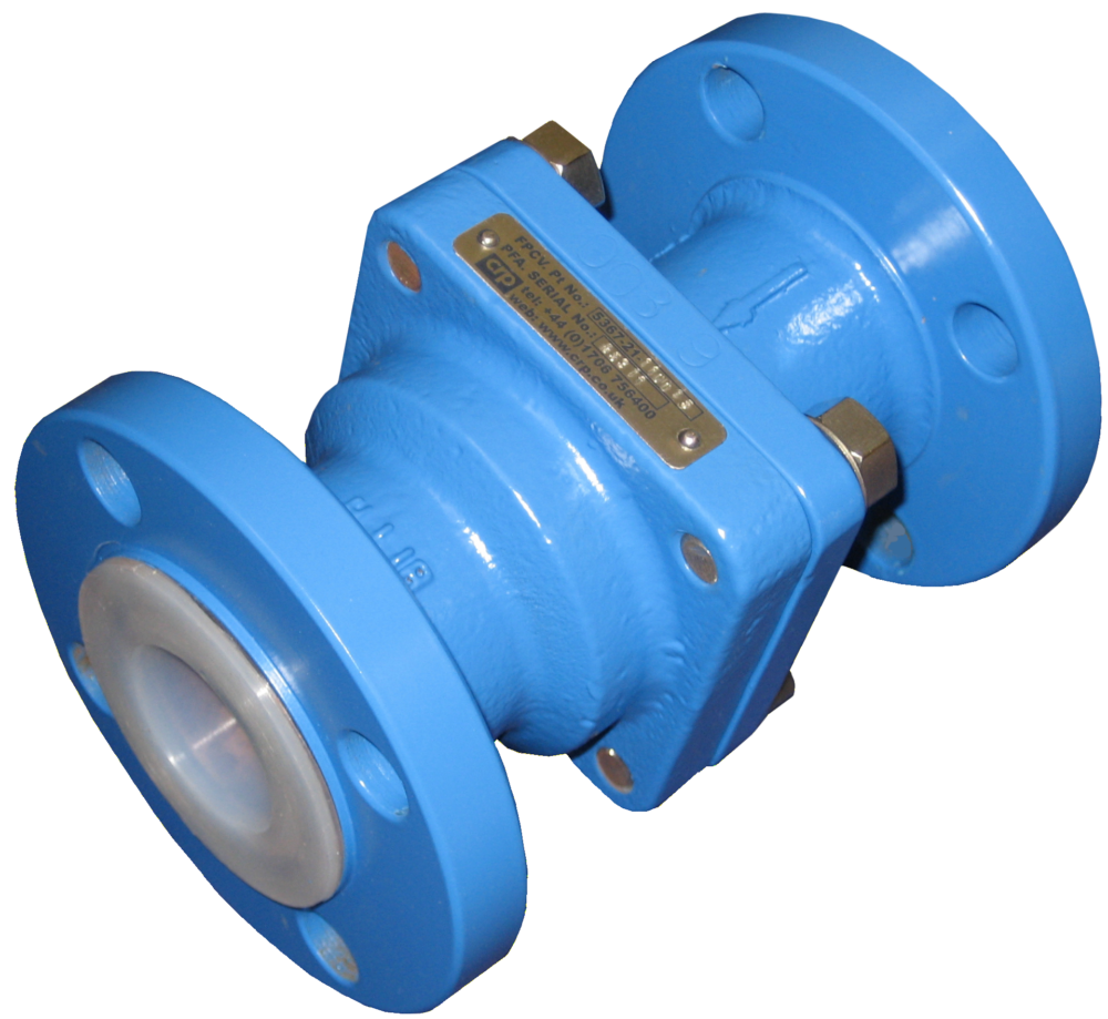
Fittings
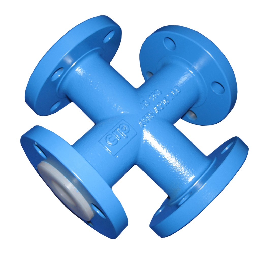
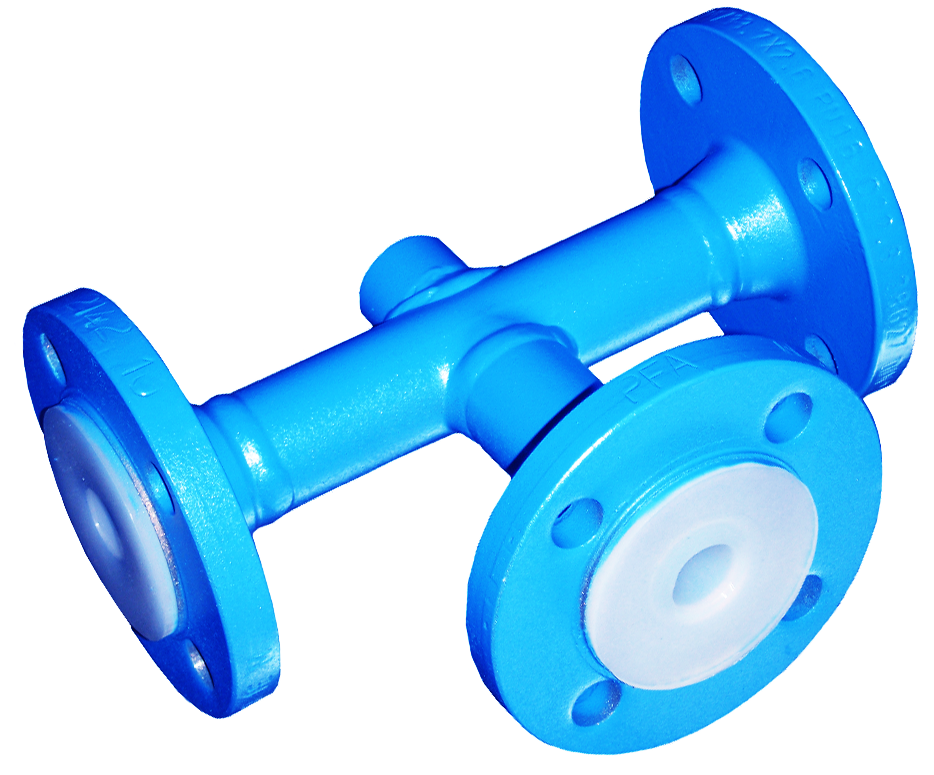
There is an extensive range of pipe fittings – elbows, tees and reducing pieces – available and it is worth considering some of the less popular ones which have specific applications. Often only the most standard items are configured on CAD piping design systems so the less popular can be neglected.
For instance, instrument tees are excellent for providing branches in confined spaces, a 6″ bore component will take up 2″ of line space, whereas the equivalent reducing tee will use up 16″ of line space. They are often used for pressure gauges, pH probes, conductivity meters etc.
The short stack tee is also excellent for confined spaces as is the reducing flange over the concentric reducer – but of course it does not provide the same flow path.
Long radius bends provide a good solution for viscous media or slurries, whilst eccentric reducers are important for pump suction, preventing air traps and dead spots in lines.
Lateral tees are often selected for run off manifolds from reactors improving the materials flow.
Finally, it may be worth considering specially produced items. These can solve particular problems and are often not expensive, using common tooling elements.
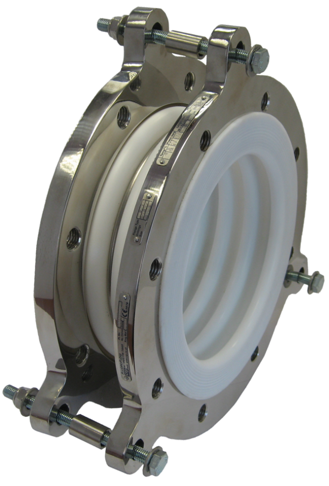
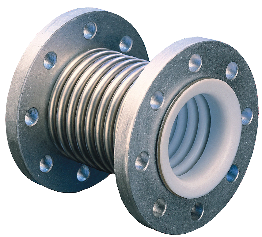
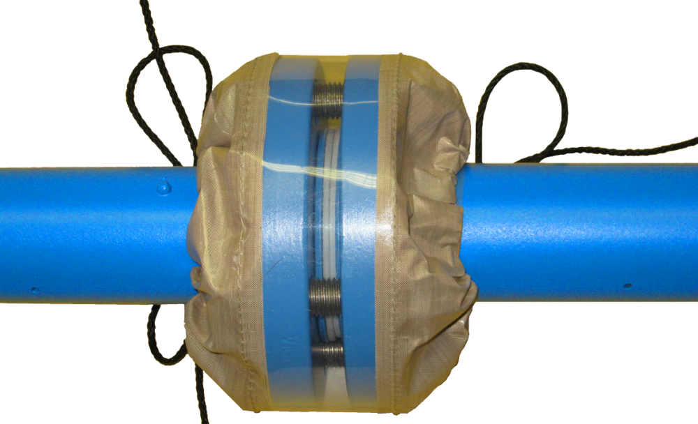
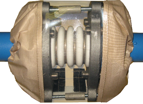
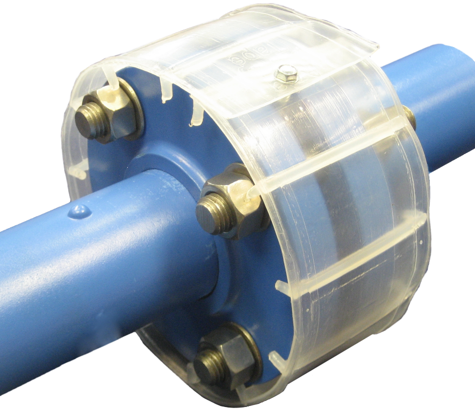
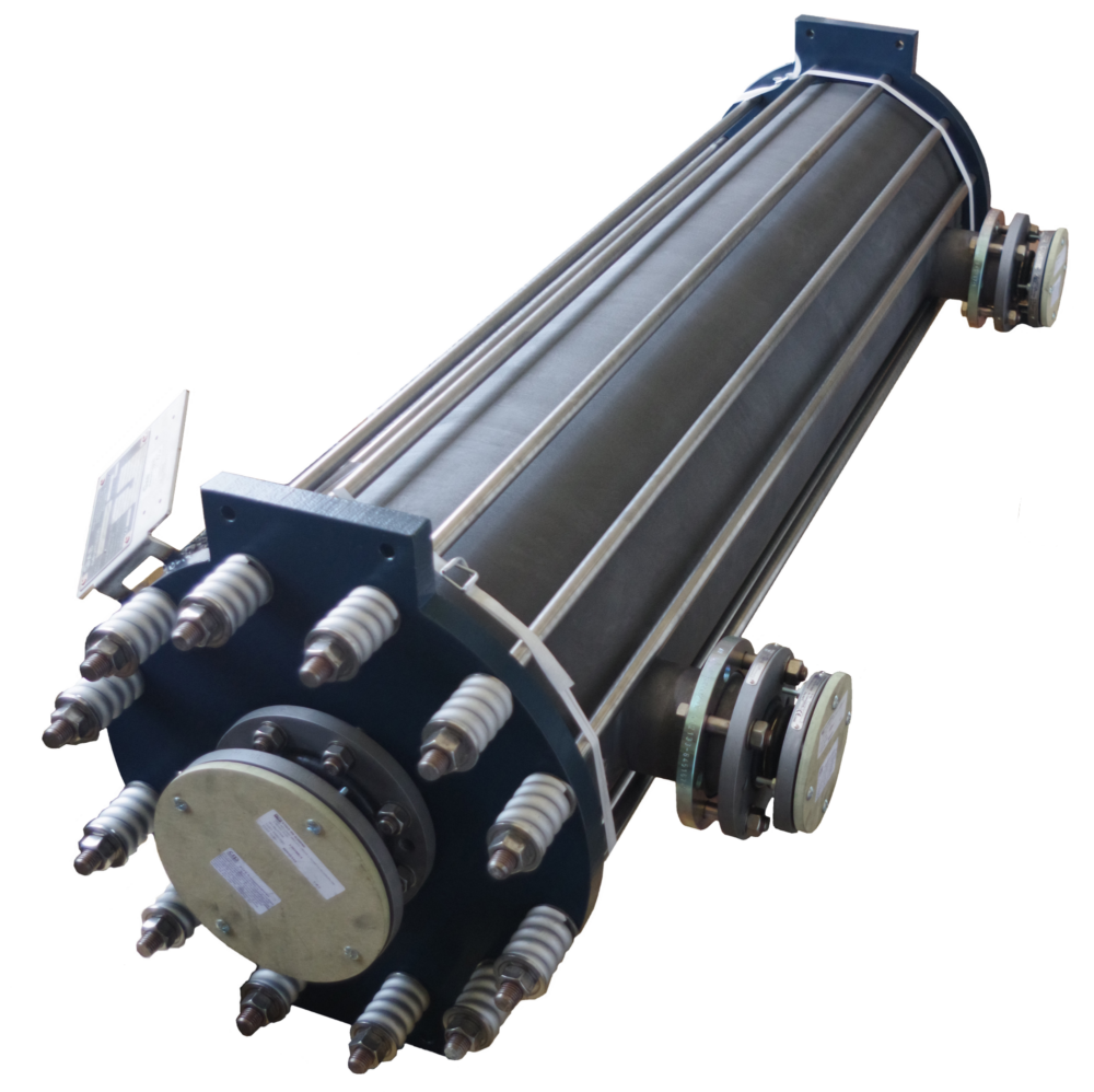
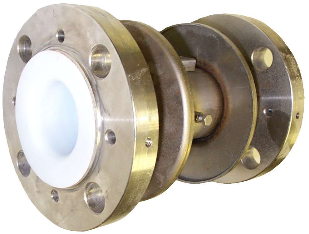
Expansion Joints
These are also called bellows or compensators and are a very vulnerable component, a source of misspecification and consequently many plant accidents. They are designed for axial, lateral and angular movements and this will be defined by the manufacturer.
They will not take the maximum range of all three movements and really only perform well with one of the movements. They will never deal with rotational forces. Bellows come with a number of convolutions – three would be considered a standard bellows. As a rule of thumb, the more the convolutions, the more movement a bellows will provide, but the lower its pressure and temperature performance.
Various reinforcements of rings and outer shells are available for high pressures, temperatures or vacuum performance. A good bellows will be designed to accept four times the rated pressure. Tie rods and hinges can be an integral part of the design limiting maximum and minimum movements or preventing movement altogether in certain planes.
Bellows liners should be considered for products that may hold up in the convolutions and certainly flange shields should always be specified alongside. As a vulnerable component the previous comments on pipe liner processing methods are even more appropriate and the best bellows are manufactured using paste extruded liners. (11)
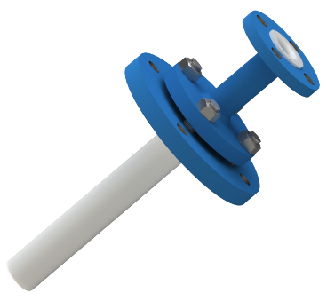
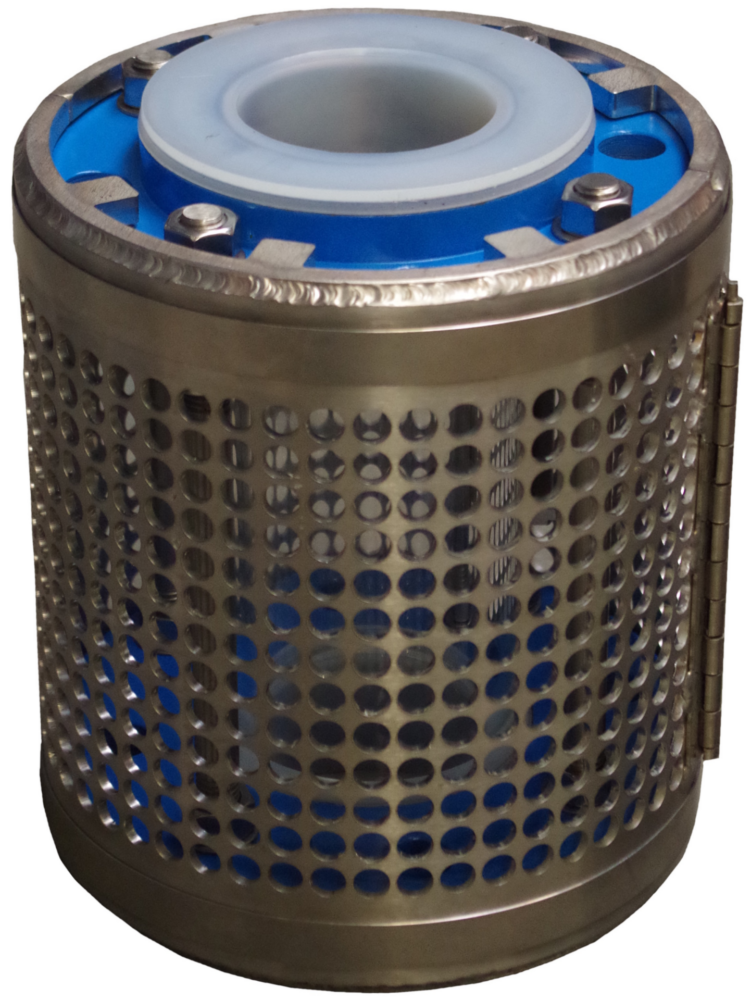
Dip Pipes
Dip pipes are used for a variety of purposes within a vessel, such as:
- for liquid/steam/gas addition with considerations of where the added fluid meets the bulk liquor in the vessel
- liquid extraction; as a means to support a spray ball for vessel cleaning purposes
- as a means to protect the vessel lining from the concentrated additive prior to it being diluted in the bulk liquor.
To this end a variety of dip pipe configurations can be offered to meet these requirements. The simplest form of dip tube can be a PTFE sleeve, flared at one end, to protect the neck of the vessel during liquid additions.
Where a spray ball is to be supported, or where a sharp change in direction is required, a machined solid PTFE construction can be considered. For longer lengths, and particularly where the dip pipe will be immersed in the liquor, and the liquor is being agitated, it is necessary to have a lined steel dip pipe to achieve sufficient mechanical strength.
Linings can be made from a continuous length of PTFE (the best type of lining since there are no potential weak spots at welded joints, but which have limitations in terms of total length available), a welded PTFE lining, or a welded FEP lining (best used where for strength reasons a large diameter pipe is required, but where for flow reasons, only a small bore is required). Due to the nature of FEP this style of dip pipe has a lower operating temperature than PTFE lined designs.
Where dip pipes are to be used in agitated vessels dip pipe manufacturers can carry out design calculations to ensure that their dip pipes are sufficiently strong to survive the mechanical loads such agitation will cause. Additionally, where high temperatures and extreme levels of vacuum will be encountered, dip pipes can be offered with an additional vacuum support tube. Similarly, dip pipes can be supplied with steam sparge pipes when required. Finally, dip pipes can be offered with a gentle curve along their length, useful if it is necessary to add liquor against the edge of the vessel, or into the eye of the agitator.
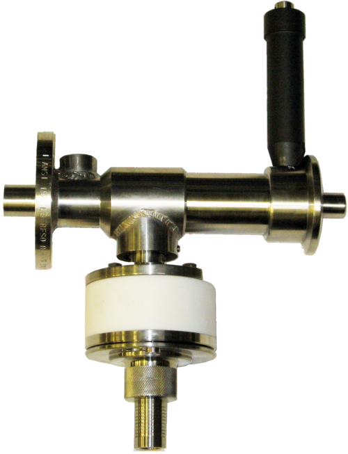
Valves
A key ingredient in any lined piping system, valves can be split into three broad families of product:
- quarter turn on/off valves
- flow control valves
- check valves.
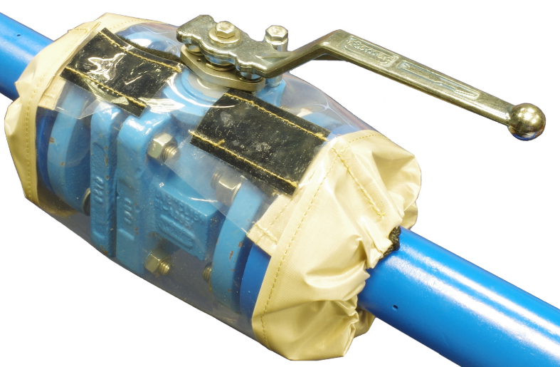
Quarter Turn On/Off Valves
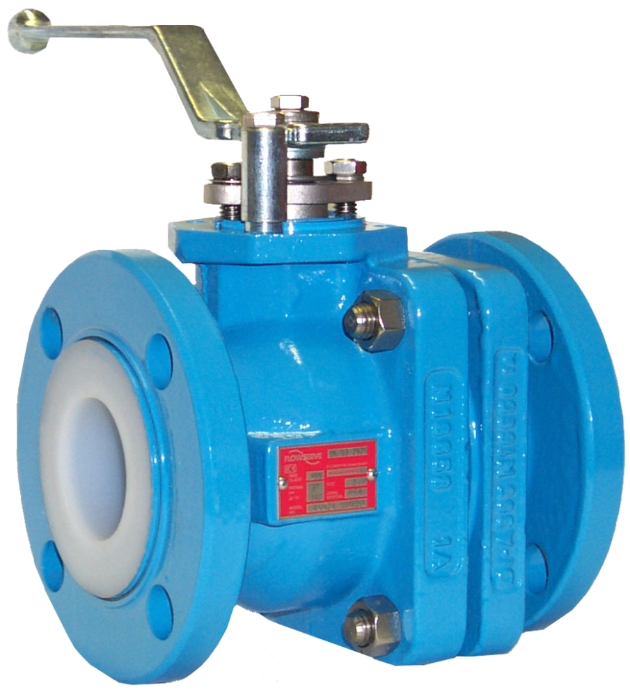
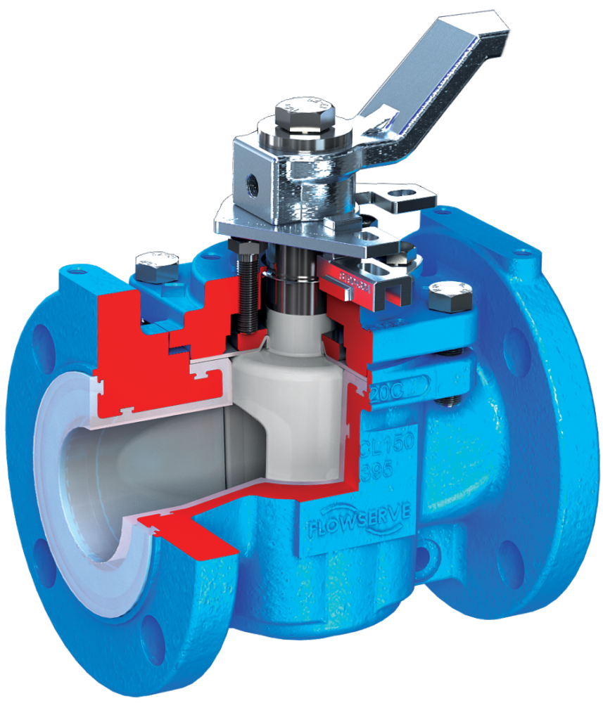
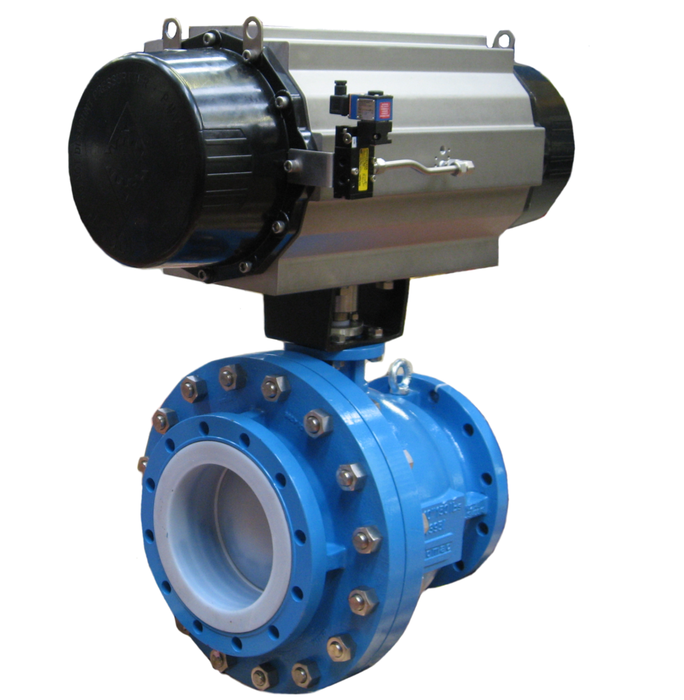
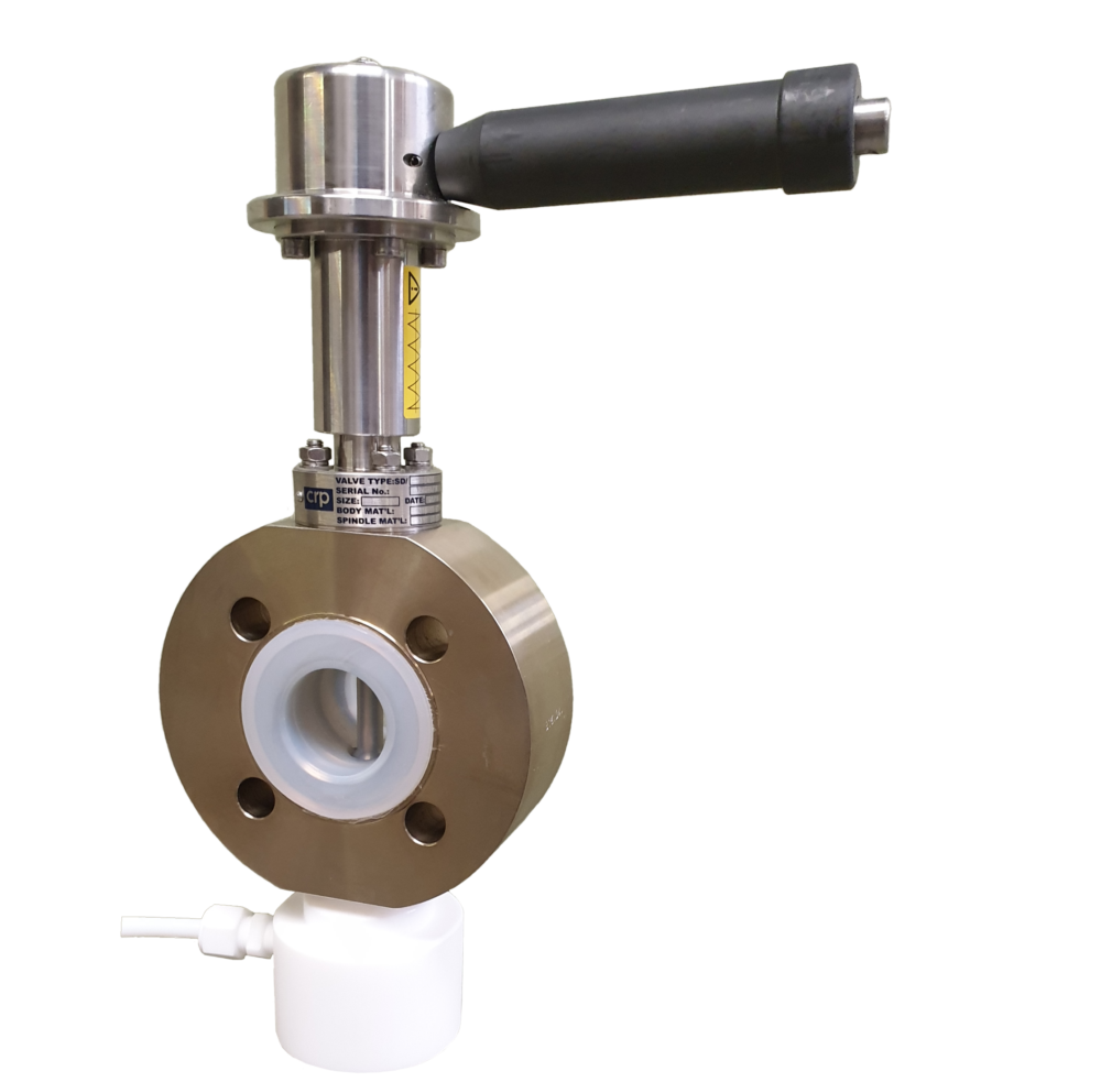
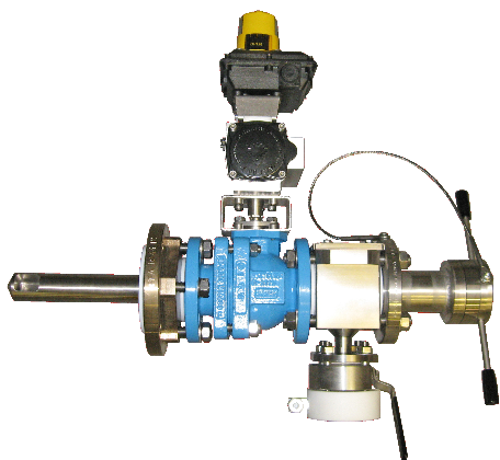
This market segment is dominated by ball valves, with their lower operating torques, straight through full bore flow paths, and good shut off performance. There is still a place for lined plug valves where absolute shut off is required, such as plant isolation and end of line duties; although this performance comes with a significant penalty in terms of turning torque.
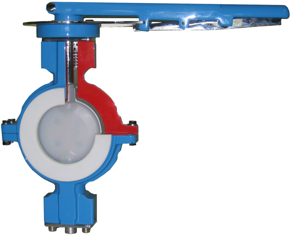
The third common type of quarter turn on/off valve is the lined butterfly valve. These are widely used for larger line sizes and for powder handling duties, due largely to their lower purchase price, but with a somewhat reduced operating envelope.
When specifying lined butterfly valves, great care must be taken to ensure that the adjacent lined components do not interfere with the valve disc when the valve is opened. Traditionally, bespoke spacers have been used to work round this problem, although in recent years some manufacturers have started to offer long pattern butterfly valves which eliminate this issue.
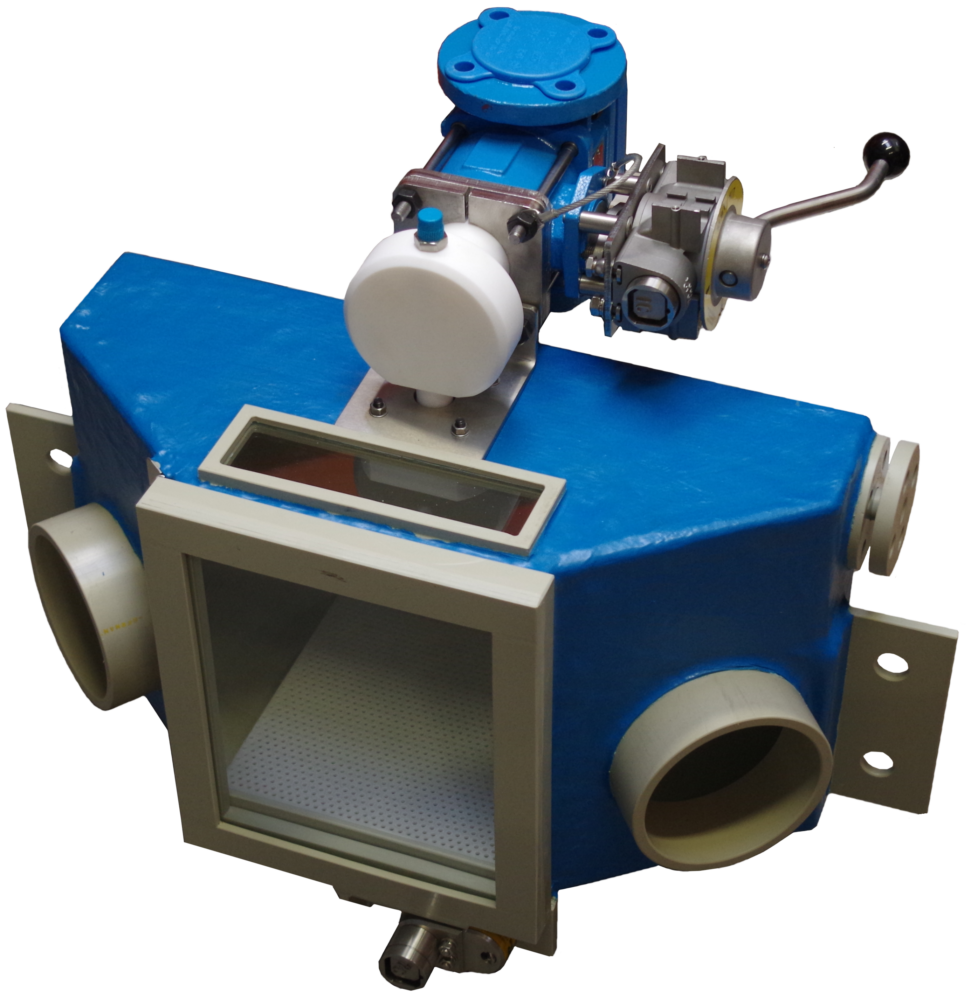
Flow Control Valves
It is important to control the flow of liquids within a piping system in many processes.
If only fairly coarse flow control is required, this can be achieved by using ball and plug valves with a characterized ball or plug. Typically, such a ball or plug will have a “V” shaped port in it, allowing for a much more linear response between valve opening and flow to be achieved.
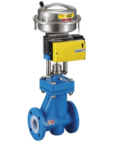
Usually such valves are supplied with a pneumatically operated actuator and positioner to allow for continual fine adjustments to the valve position to achieve the required flow. Finer flow control can be achieved by the use of actuated PFA lined globe control valves where different trims can be specified to achieve defined flow characteristics.
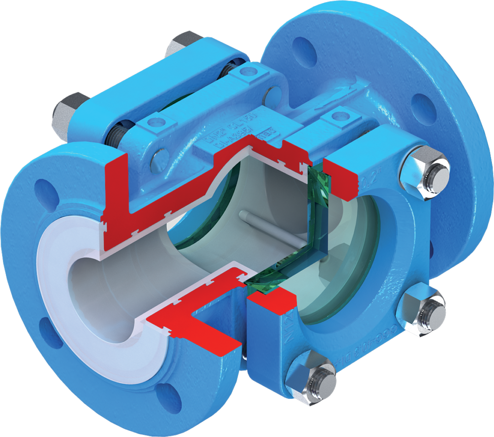
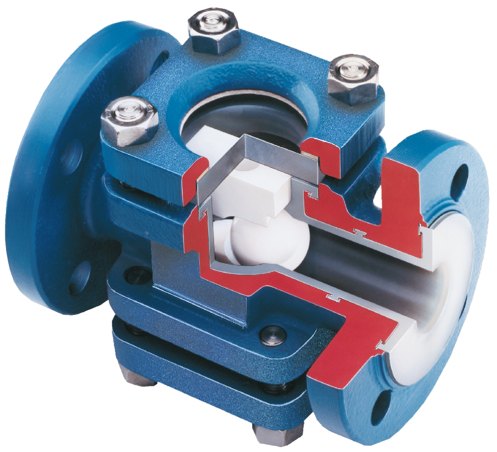
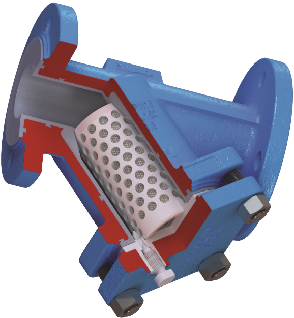
Check Valves
Check valves are the final common class of valve that is found in lined piping systems. They come in several forms all of which fulfil the same basic purpose, namely to allow forward fluid flow, but minimize backwards flow.
The most common types of these valves are:
- poppet check valves
- swing check valves
- ball check valves
Poppet check valves have a poppet that is pushed forwards by the forwards fluid flow, allowing fluid to flow around it and on down the process line. If the flow of fluid ceases, the poppet reseats preventing backwards flow. In most cases this closing of the poppet is aided by a spring, which also allows the cracking pressure of the valve to be chosen to suit the particular process, and also allows the valve to operate in any orientation.
Ball check valves operate in the same way as poppet check valves, except that the poppet is replaced by a ball, and they usually do not have a spring to help with valve closing, limiting their use to vertical lines with upwards forward flow.
Swing check valves have a disc that rotates or swings out of the fluid flow in the forwards flow direction, but that swings back against its seat to prevent backwards flow. These valves work well in vertically rising forward flow. In some cases, the valves can also be used in horizontal lines, provided they are designed with an angled seat.
In all cases it is important to note that check valves only check backwards flow, and so they cannot be relied upon to provide a complete back flow shutoff, although depending upon the exact conditions, in many cases they may well achieve this.
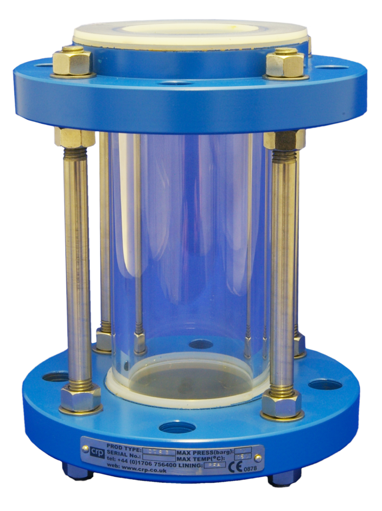
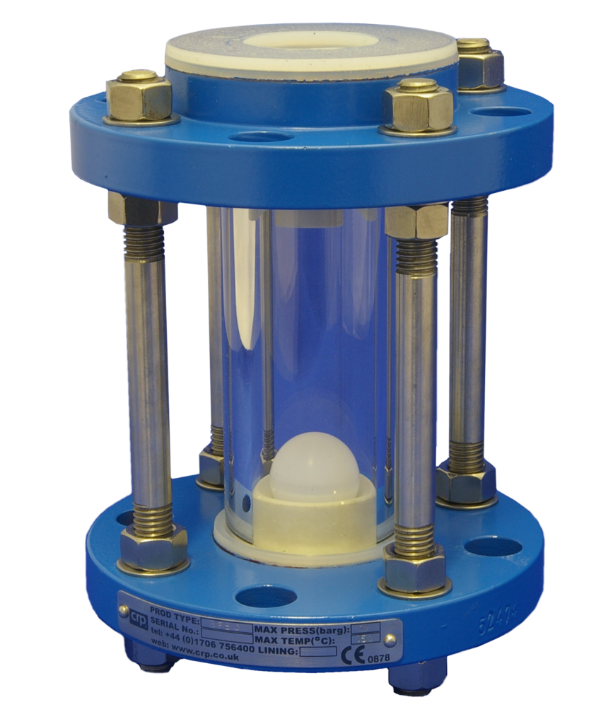
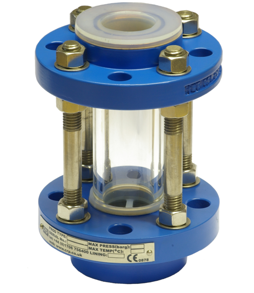
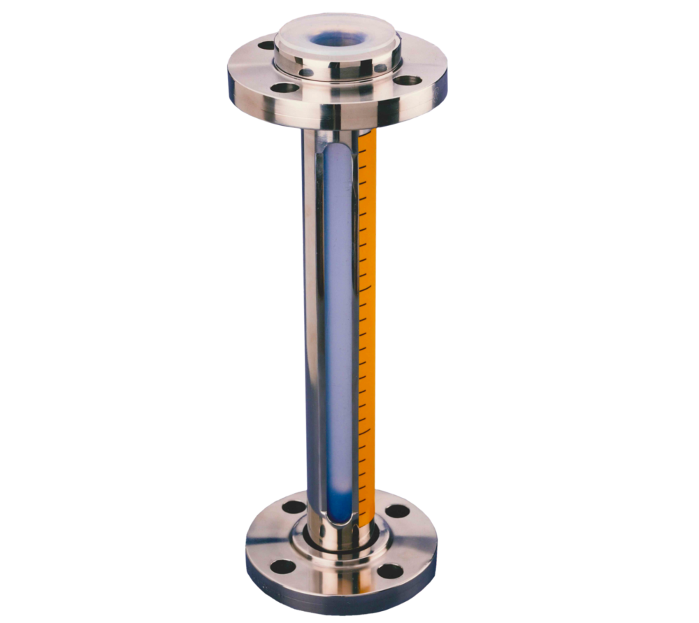
Sight Glasses
Several types of sight glass can be provided for lined piping systems to address the needs of process engineers and chemists who like to be able to see what is happening within their process plant.
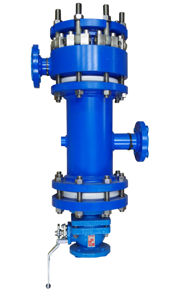
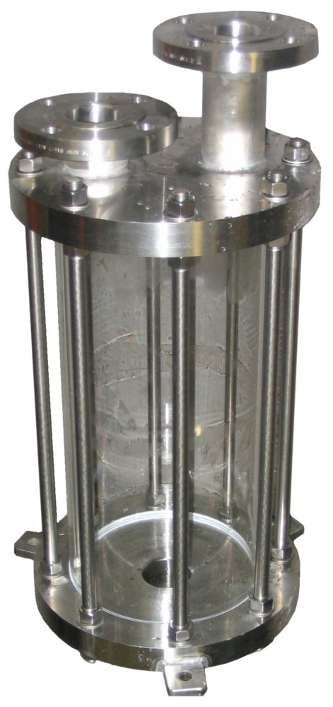
Tubular sight glasses, comprising a heavy-duty borosilicate glass tube securely held within a support framework of PFA lined end flanges and tie rods, provide the best all round viewing, but are somewhat limited in terms of their pressure and temperature capabilities.
For higher pressure and temperature duties two, three and even four-way versions of bull’s eye sight glasses can be supplied. For duties where the process liquor would attack the glass, sight glasses can be supplied with a protective inner layer of PFA or FEP. For duties where glass is not acceptable in the process, a range of tubular sight glasses and level gauges can be provided which comprise of a PFA tube surrounded by a protective metallic outer housing. Depending upon the precise configuration of the housing, the pressure temperature envelope of these sight glasses can be made to be broadly comparable with those of tubular sight glasses
Installation
Whilst the installation of lined equipment is not strange or complicated, there are sufficient special considerations to have the potential to cause irreparable damage to lined products if the installer is ignorant of these.
All European manufacturers are obliged to provide user instructions and reputable manufacturers should also provide training. Specific training courses are available for activities such as field fabrication of pipe spools, plug valve repair and sampling valve specification.
The general guidance should be to assume that your installer is unfamiliar with this equipment unless the correct training records can be produced to prove otherwise.
Summary
When specifying lined equipment for the first time, it should be treated in the same way as buying any other piece of unfamiliar equipment.
First establish the need, next consider the appropriate materials and processing methodology. Create a specification and purchase against it. Wherever possible visit the manufacturing plant or their distributors operation to understand the level of process control, testing and general product traceability.
With the appropriate equipment you should be able to fit and forget.
References
- Ebnesajjad, Sina. Roy Plunkett’s World. 2007.
- Driebeek, Jeanne. Teflon FEP, PFA and Tefzel Product Family. Presentation. Geneva : s.n., October 14, 2008.
- Ebnesajjad, Sina. Fluoroplastics Volume 1 Non-Melt Processable Fluoroplastics. Norwich, NY : Plastics Design Library, 2000.
- Fleming, James R, et al. Materials of Construction for Pharmaceutical and Biotechnology Processing: Moving into the 21st Century. Wilmington : DuPont, 2001.
- DuPont – An End-user of Teflon. Khaladkar, Pradip. Frankfurt : s.n., 2009. Achema Conference.
- Ariawan, Alfonsius, Ebnesajjad, Sina and Hatzikiriakos, Savvas. Properties of Polytetrafluorofthylene (PTFE) Paste Extrudates. Polymer Engineering and Science. June 2002, Vol. 42, 6, pp. 1247-1259.
- Sperati, Carleton A. Physical Constants of Flurorpolymers. Parkersburg : DuPont, 1981.
- DuPont. Properties Handbook. Wilmington : DuPont, 2004.
- Pavey, Ian. Electrostatic Hazards in the Process Industry. Transactions IChemE, Part B, Process Safety and Environmental Protection. 2004, Vol. 82, pp. 132-141.
- —. Electrostatics. [interv.] N Price. July 7, 2009.
- PTFE Lined Equipment (Columns and Vessels) for the Chemical Process Industry; Advantages/Disadvantages of Paste-Extruded PTFE. Bruemmer, Michael. Houston : NACE International, 1999. Corrosion 99.
- Ebnesajjad, Sina. Introduction to Fluropolymers. 2006.
- DuPont. Teflon A Performance Guide for the Chemical Processing. Wilmington : DuPont, Undated. E-21623-2.
- Khaladkar, Pradip. Fight Corrosion with Plastic. Chemical Engineering. October 1995.
- DuPont. Teflon/Tefzel Corrosion Prevention in the Chemical Industry. Geneva : s.n., 1990.
- Buxton, William and Henthorn, Gregory. Get the Most Out of Plastic Lined Pipe. Chemical Engineering. September 1994.
- Korinek, Paul. Fluoropolymer Linings – the Exceptions Prove the Role. Process Industry Journal. March 1990.
- Dyneon. Processing of Dyneon PTFE Fine Powder. Burgkirchen : s.n., 2005.
- Neumann, Wolfgang. Dyneon PTFE – Fine Powder and Processing. s.l. : Dyneon, 2007.
For further information on the subject of the properties of PTFE – https://www.teflon.com/en/industries-and-solutions/solutions/chemical-thermal-resistance