


Permeation Within Lined Piping
In certain circumstances permeation through fluoropolymers can be a common issue with lined piping systems. Here we will explain the factors that lead to this permeation with particular consideration given to:
(i) the mechanisms of permeation
(ii) factors that influence the rate of permeation, and
(iii) a discussion of the relative merits of different fabrication methods used in manufacturing fluoropolymer lined piping systems with regard to permeation.
Nb. It should be noted that what follows will only give consideration to PTFE and PFA.
(i) Mechanisms of Permeation
Polymer Structure
It is necessary to understand the basic chemical structure of these materials to understand how molecules can permeate through fluoropolymers. The diagrams below show that both PTFE and PFA are made up of long chains of carbon atoms, surrounded by fluorine atoms.
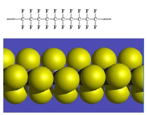
Each carbon atom in the chain (which may be a thousand or more atoms long), has two fluorine atoms bonded to it. Given that:
(1) the carbon carbon bond is strong and the carbon fluorine bond is one of the strongest chemical bonds known,
(2) the resulting molecule is very simple in structure (only carbon and fluorine atoms) and
(3) the shape of the molecule is such that the exterior of the molecule is made up of a closely packed helical sheath of fluorine atoms protecting the carbon atoms that make up its backbone,
the result is an extremely strong molecule, that is almost entirely impervious to chemical attack.
When PTFE and PFA molecules are in their bulk form, they comprise a mixture of crystalline and amorphous (non-crystalline) components. When these two structures are examined in detail, it is found that the crystalline components are denser in comparison to the amorphous ones.
As a result of its unique structure, there are 3 distinct ways in which permeation can occur:
Permeation Type 1
Physically very small molecules, such as helium, water or carbon dioxide can permeate through PTFE and PFA. This occurs because the molecules are small enough to allow them to pass between the individual polymer molecules within the structure of the polymer. This type of permeation is largely absent in the crystalline components of PTFE and PFA. This has been observed because within crystals the individual molecules form an orderly structure, leaving little space for other molecules to pass through. In the amorphous components, the molecules are arranged in a random fashion, resulting in a structure that is about 15% less dense than the crystalline one, thus leaving more space between individual polymer molecules, making the structure more permeable.
These very small molecules permeating through the structure of PTFE and PFA do not cause any damage to its structure, its corrosion resistance and its non-stick properties.
Permeation Type 2
Some atoms can permeate through the structure of PTFE and PFA; namely those that are chemically similar to fluorine, such as chlorine and bromine. Here the permeation mechanism is one of substitution of atoms in the polymer chains. For example a chlorine atom can take the place of a fluorine atom on a PTFE polymer chain on the surface of the PTFE. It can then jump from there to a PTFE molecule further into the structure, and so on through the entire thickness of the material.
At a molecular level individual atoms transferring between molecules is quite normal, in this case fluorine atoms jumping from one PTFE molecule to another. Therefore, the transfer of other atoms through the thickness of the PTFE does not cause any damage to the overall structure of the polymer.
Permeation Type 3
This is not strictly permeation by definition, although the end result is the same: the movement of material across the thickness of a polymer layer. The mechanism here is the movement of material through cracks and voids in the bulk polymer, these flaws being present due to poor manufacturing technique. This topic will be covered in greater detail in section (iii) below.
(ii) Factors Influencing the Rate of Permeation
Governing the rate at which materials can permeate through the thickness of a piece PTFE or PFA are a wide variety of factors, which result in greatly varying rates of permeation.
A piece of lined equipment can stay in service for 20 or more years showing no evidence of permeation. There are circumstances where permeation will become evident in a matter of weeks or months after a piece of equipment is put into service. Over the course of many years of research, the following factors have been found to have a major influence on the rate of permeation:
- The polymer layer thickness
- The temperature
- The pressure differential across the polymer layer
- The concentration of permeant in the contained fluid
Dealing with each of these in turn:
- Polymer Layer Thickness
If two polymer layers, made of identical material, fabricated in the same manner were tested for rate of permeation, it would be found that the rate of permeation through the thicker layer would be lower than that through the thinner layer. In most circumstances the fall off in permeation rate is non-linear with thickness, often decaying in roughly logarithmic manner. However, as the thickness continues to increase it has been found that the permeation rate tends to plateau, rather than continue to fall.
- Temperature
As the temperature increases, the rate of permeation through PTFE and PFA increases, in a non-linear fashion. This is driven by several factors, namely, as the temperature increases (a) the permeant will become more soluble in the polymer, (b) there is an increase in the amount of swapping of individual atoms between the polymer chains, and (c) the polymer increases in volume, leading to more space between the individual polymer chains giving more space for atoms to pass between them. It should be noted that not all these mechanisms may occur in any one particular set of circumstances.
- Pressure Differential Across the Polymer Layer
As the pressure differential across the polymer layer increases, the rate of permeation through PTFE and PFA increases in a roughly linear fashion in most circumstances.
- Permeant Concentration
As the permeant concentration in a liquid, or partial pressure of a gas increases, the rate of permeation increases in a linear fashion.
Important Note
Where the above factors are concerned, it has to be mentioned that most research work that has been carried out into permeation rates has been on polymer layers ranging from a few tens of microns thick up to a few tenths of a millimetre thick. The results obtained are, on the whole, extremely variable, and owe much to the method of fabrication of the test membrane, and the exact test methodology used. Attempts to translate this thin film data into meaningful data for liners used in piping systems (with liners typically ranging from 3 – 10mm thick) have proved to be singularly unsuccessful.
(iii) Fabrication Method and Permeation
We will consider 3 different methods of creating a lined piping component in this article:
- Transfer moulding of PFA
- Paste extrusion of PTFE
- Isostatic moulding of PTFE
Ram extrusion and tape wrapping have also been used in previous years to produce liners for PTFE lined equipment. CRP has found both production processes to be inferior, and have now largely been abandoned.
A well-made piece using any of the manufacturing methods named above will result in good permeation resistance, provided that their manufacture and materials of construction are of the highest quality. Similarly, low quality materials and/or poor manufacturing processes will result in unsatisfactory components and potential premature catastrophic failure.
For severe service conditions it is recognised that PFA has better permeation resistance than paste extruded PTFE which in turn has better permeation resistance than isostatically moulded PTFE.
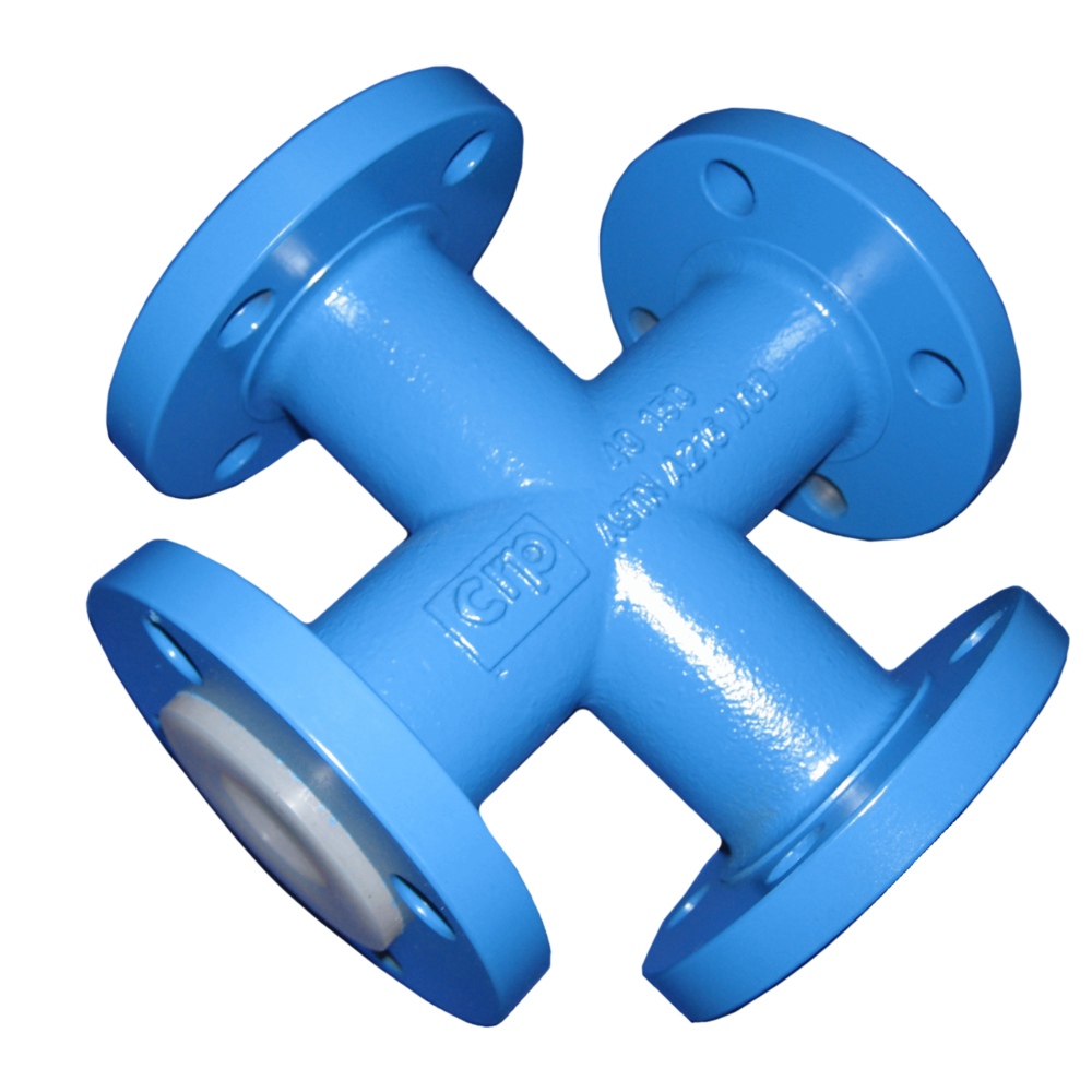
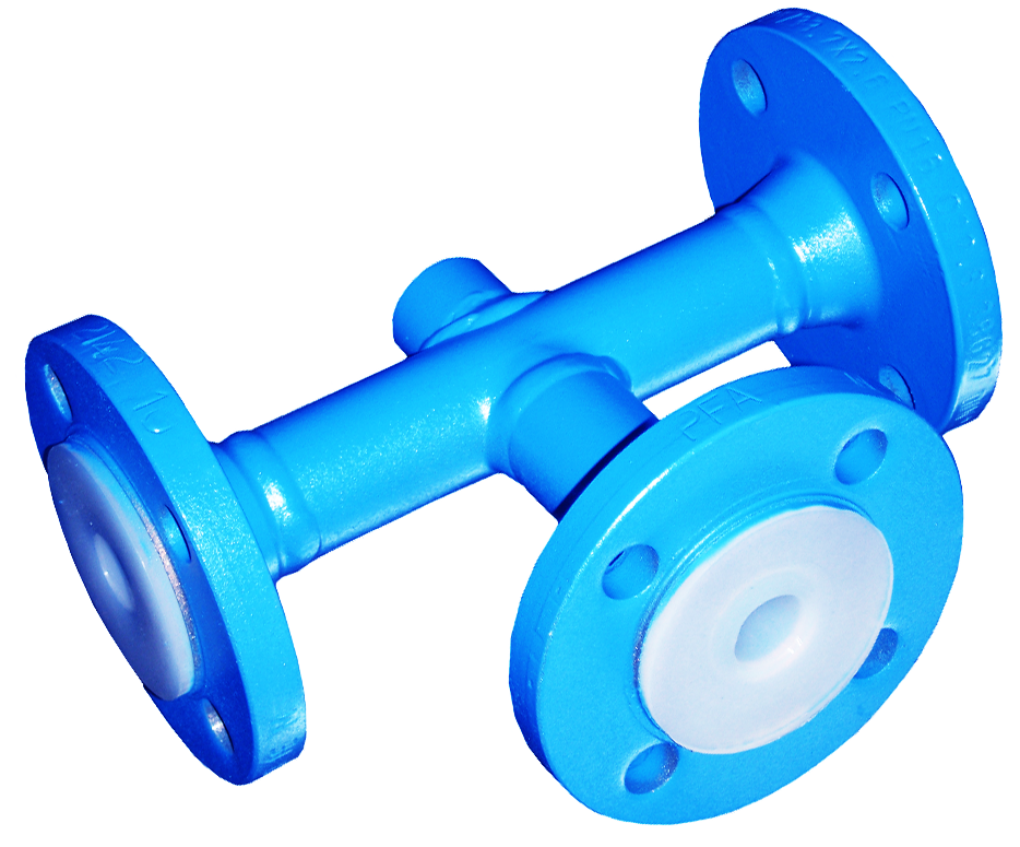
- Transfer Moulding of PFA
PFA is usually only used to manufacture lined fittings, rather than straight pipe spools. When creating a PFA lined pipe fitting, the fitting and the moulding tooling are assembled together. They are heated to the correct temperature, typically in an oven and then molten PFA is injected into the fitting, and the lined fitting cooled in a controlled manner.
Key variables that need to be controlled to give a top quality product are:
- The quality of polymer used in the moulding.
In general terms the higher the molecular weight of the polymer used, the higher the resistance to chemical attack and permeation, but the harder it becomes to transfer mould the polymer. CRP uses only the highest quality, highest molecular weight polymers available on the market. - The geometry of the fitting relative to the moulding tooling.
Where there is significant dimensional variation from fitting to fitting, this can result in thin sections of the liner due to misalignment between the moulding tooling and the fitting. To ensure consistent, and top quality moulded fittings, CRP has invested in a wide range of cast steel fittings manufactured using the lost wax method, which provide extremely consistent geometry thus eliminating this issue. - The injection pressures and temperatures used during moulding.
The use of excessive injection pressures can force PFA rapidly into a fitting. Similarly, it is possible to force PFA into a fitting that is not hot enough. In both cases, the PFA will still flow into the fitting, however, its corrosion and permeation resisting properties will be severely compromised due to the damage caused by the shearing of the polymer during the moulding process and the high levels of residual stress remaining in the component after manufacture. To avoid these errors, CRP uses sophisticated, calibrated temperature and pressure control systems on all of its pre-heat ovens and moulding equipment to ensure the correct temperatures and pressures are used throughout the moulding process. - Cooling of fittings during the moulding process.
If a fitting is cooled incorrectly, this can result in high residual stresses in the lining or, in extreme cases, can result in shrinkage voids in the lining. To ensure low stress linings without voids, CRP uses bespoke designed moulding tooling combined with many years of moulding expertise.
To ensure product consistency covering the above features, over many years CRP has invested heavily in automated and semi-automated moulding equipment to minimise the chance of operator error and to ensure mould to mould product consistency. In addition, due to the translucent nature of PFA, it is possible to visually identify many of the potential faults described above, and therefore CRP uses a system of best practice inspection and test of all moulded fittings as detailed in international standards.
- Paste Extrusion of PTFE
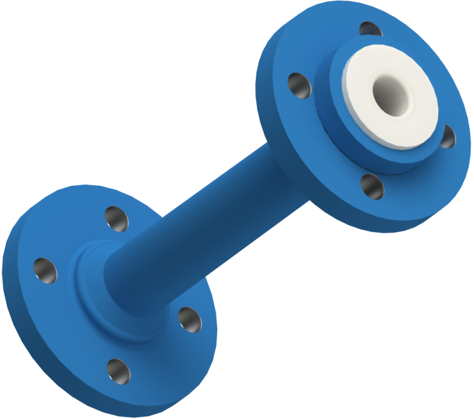
When making straight pipe spools and pipe fittings without branches, paste extruded PTFE is almost always used. To create these components, a quantity of paste extrusion grade PTFE (typical particle size 0.2 micrometre diameter) is weighed into a mixing container, and a quantity of lubricant added to it.
The mixture is then gently mixed together and then left to “condition” ie for the lubricant to fully soak into the PTFE particles. The PTFE/lubricant mixture is then compressed into a billet, the billet is placed in an extruder and the desired liner extruded through an appropriately sized pin and die, typically into a carrying tube. The liner is sintered then pulled into a spool or fitting. Finally, the flare faces on the ends of the spool or fitting are created by manipulating the PTFE with heat and tooling.
Key variables that need to be controlled to give a top quality product are:
- The quality of polymer used.
Paste extrusion grade polymers are the most refined and have the most closely controlled production processes of any grades of PTFE polymer, and thus paste extrusion grades of polymer are inherently the highest quality of polymer available. CRP only use polymer purchased from world class polymer manufacturers, and which contain no reclaimed polymer. - The quality of lubricant used.
During the sintering process, all of the lubricant evaporates off. If something other than very clean lubricant is used, any non-volatile residues will be left behind causing defects in the finished liner. CRP use only the highest quality and cleanest lubricants available, which leave no detectable residues in the finished liner.
• The mixing temperature.